 DTCEE



2-Pin Industrial Socket: What To Verify Before Buying
When you see that the terminal block has only two clearly visible contacts, or the purchase order simply lists “2 pin,” it’s easy to instinctively assume it’s a two‑hole industrial socket. However, the number of pins seen by the naked eye, the number of working poles actually carrying current, the protection of grounding electrodes (PE) and the phase system of the power grid are completely different concepts in industrial standards. If you place an order based solely on appearance, even if the product you receive matches in color and is similar in size, it’s highly likely that it won’t fit, won’t connect properly, or will have completely mismatched wiring definitions.
A compliant and prudent approach to selection involves first translating verbal or commercial descriptions into precise engineering specifications, and then determining the socket type and installation method based on these specifications.
First, Verify Exactly Which Contacts Are Included In The So-Called “2 Pin”
In industrial electrical connections, standardized polarity markings are far more critical than verbal references such as “two-core” or “two-pin.” Taking the common “2P E” configuration as an example, it consists of two live poles and one protective earth pole, physically comprising three main contacts. In a single-phase circuit, the two live conductors serve different electrical functions. The specific wiring configuration on site must be verified based on the power supply system type, the equipment nameplate, and the electrical wiring diagram; it should not be inferred arbitrarily from the mere designation “2P E.”
Therefore, when checking the industrial socket with the supplier, the other party must be required to make it clear in writing: does the so-called “2 pin” refer to two working contacts, or is there only two visual contacts in the whole shell? Does the product have an additional protective grounding electrode? Is the official specification marked 2 P, 2 P E or other configuration? The neutral line (zero line) and the protective grounding line (ground line) have completely different functions, and must not be mixed or substituted in order to make up the number of contacts.
This also helps to dispel a common cognitive bias: single-phase power does not imply a fixed number of pins, nor can the number of pins be used to conclude that a product is necessarily suitable for a single-phase circuit.
The Installation Of The Socket And Its Mounting Structure Have Not Yet Been Finalized
“I industrial socket” merely specifies the broad category of the power connector; it could be a fixed‑installation outlet connected to a permanent conduit, or a portable outlet (socket connector/female end) attached to a flexible mobile cable. If the component is mounted on a cabinet or panel, it must be further classified as either a panel-mounted socket with female contacts or an appliance inlet socket with male pins.
First, check whether the front of the product uses a socket or pin configuration; then examine the wiring layout on the back and the overall mounting method. If it is to be installed on the outer surface of the wall, rack or equipment box, the open wall socket with independent inlet structure and complete bottom box shall be selected; if it is to be embedded in the door panel of the control cabinet or equipment operation panel, the flange shape, the opening size of the box, the bolt fixing hole distance, the protruding depth of the back of the panel and the wiring bending allowance shall be checked. The structural differences between straight‑through and angled designs directly affect the cable insertion/extraction direction, the opening angle of the splash guard, and the available bending space for on‑site cabling.
Avoid using the vague terms “male connector” or “female connector.” In physical mating, one side does indeed have pins while the other has sockets; however, plugs, portable outlets, fixed outlets, and appliance inlet sockets each serve distinct purposes—whether for flexible-cable connections, fixed wiring, or direct power input to the device body. Their roles are entirely different.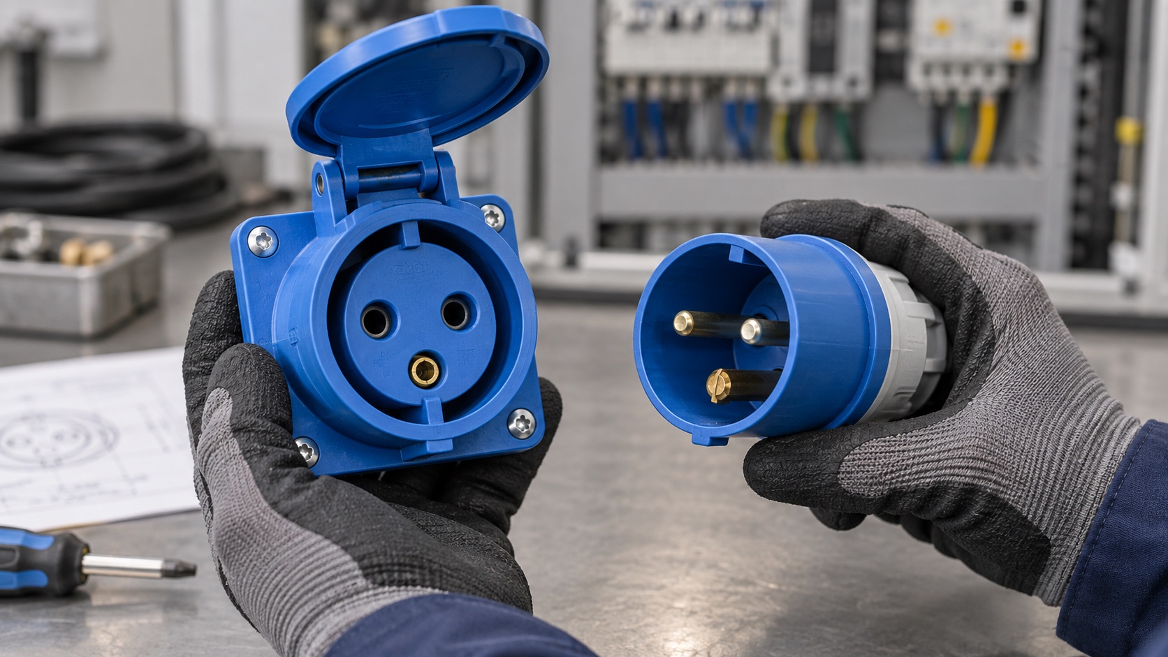
Complete The Electrical Parameters Into A Full Data Table
After polarity has been confirmed, it is essential to verify each item, including the rated current, rated operating voltage, power grid frequency, and the clock position (hour position) of the grounding electrode. Interfaces conforming to IEC 60309 (or corresponding national standard) specifications rely on the clock position and the shell anti-misinsertion keyway to distinguish different electrical systems; the shell color is only used for the initial screening voltage range and cannot replace the complete parameters on the nameplate.
Take the common 50 Hz / 60 Hz configuration as an example: the same is 2P E, the electrical accessories rated 200 V ~ 250 V adopt the 6 o’clock (6h) position, while the accessories rated 100 V ~ 130 V adopt the 4 o’clock (4h) position. The two have exactly the same number of poles, but their operating voltage ranges and clock positioning are entirely different. Furthermore, the rated current directly determines the physical dimensions of the connector housing; never attempt to mate two connectors simply because their housings appear similar.
The procurement specifications shall, at a minimum, include the following items: product type, male or female connector, rated current, operating voltage, frequency, standard polarity designation, ground pin position, and the required degree of protection. As long as any of them is in doubt, the specification of the specific model, the real picture of the nameplate or the clear picture of the front of the interface should be obtained first, and it is strictly forbidden to use the real object to blindly insert and try and make mistakes.
The Protective Performance Shall Be Evaluated In The “Fully Assembled And Ready-To-Use” Condition
IP44, IP65, or IP67 ratings only indicate the enclosure’s degree of protection under specified test conditions; they do not account for dimensional tolerances, mechanical impact resistance, or chemical corrosion resistance, nor do they imply suitability for prolonged immersion in water. Whether the socket can maintain the established protection after it is put into use depends on the sealing condition of the flange gasket, the elasticity of the sealing ring, the torque of the fixing bolt, the sealing joint of the cable inlet, the sealing condition of the spare knock-off hole plug, and the closing and locking state of the flip cover or locking ring.
If it is connected to a moving cable, it is necessary to check whether the outer diameter of the cable, the cross-sectional area of the conductor, the number of cores and the type of sheath match the clamping mechanism and the stress relief structure. If it is panel installation, it must be confirmed that the opening and bolt fastening scheme will not weaken the protection level of the original electrical box. No matter how high the IP rating, it cannot compensate for defects caused by polarity errors, mismatched electrical ratings, or improper installation and assembly.
Check The Whole Set Of Plug-In Pairs To Avoid Evaluating Only The Socket Unit
Whether the socket can be finally put into use depends on whether it is completely matched with itself, the parts plugged with it and the whole power supply line. Check whether both parties belong to the same industrial standard system, confirm that the rated current, pole number, voltage, frequency, clock position, positioning slot (key position) and contact arrangement are completely consistent, and confirm that one side is the needle end and the other side is the hole end physically.
During the trial insertion, if alignment cannot be achieved smoothly, you must stop immediately. It is strictly prohibited to trim or remove the anti-misinsertion key, disassemble the guiding mechanism, modify the latch structure, or forcibly and forcefully insert the component. If the task involves replacing an existing on-site interface, the most reliable approach is to meticulously record the complete part numbers of both the original outlet and its matching plug, then systematically compare them against the on-site power cabling and equipment wiring requirements item by item.
Before formally issuing the purchase order, be sure to require the supplier to replace the ambiguous “2 pin” designation with the standardized electrical polarity code and to provide the exact model number of the mating plug or connector. Until these two factors are clarified, the socket selection process remains incomplete.