 DTCEE



Distribution Box Pre-Energization Inspection Guide
The enclosure is mounted, the door opens and closes, and the sockets and breakers all appear to be in place. At this point, it is easy to assume that the unit is ready to energize. Yet installation can change the condition of cable seals, terminals, protective conductors, and circuit labels. One missed item may leave a weakness in an assembly even when every individual component looked acceptable before installation.
A field inspection of a distribution box should follow a clear path: enclosure, wiring, protection, function, and records. This is more than a visual check, and it is not a matter of applying one generic test value to every enclosure. The objective is to confirm that the installed assembly still matches its design documents and the requirements for the actual model.
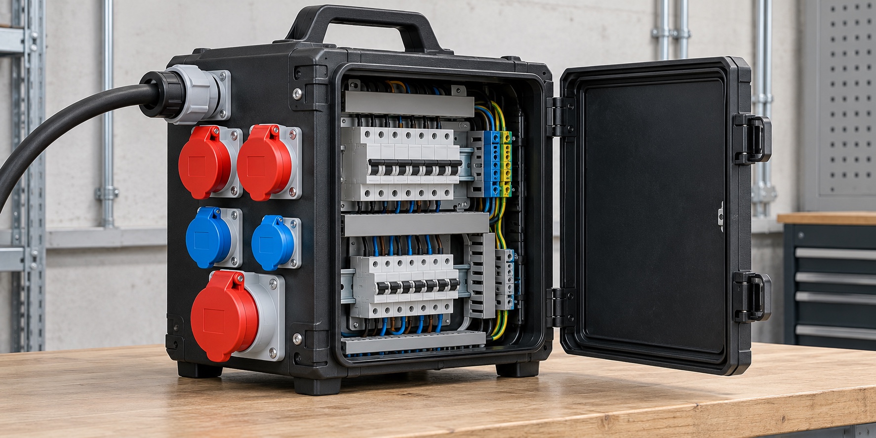
Check the External Condition Before Opening the Door
Begin with the parts that can be inspected without approaching internal conductors. Look for cracks, deformation, water entry, or signs of impact. The door, covers, locking rings, and operating mechanisms should move as intended. Each cable gland must suit both the entry thread and the cable diameter, while unused entries need suitable blanking devices for the required protection condition.
External cables should not transfer continuous pull or twist to the terminals. On a mobile unit, check whether a cable has been run over, cut by a sharp edge, or left in standing water. If the enclosure is damaged, a seal has failed, or water has entered, keep the unit de-energized and correct the defect. Temporary wrapping is not a substitute for the specified sealing structure.
Confirm That the Wiring Matches the Actual Circuit
Before approaching internal parts, isolate every source that could energize the work area, prevent unintended reconnection, and use suitable test equipment to verify the absence of voltage. Moving a switch or breaker inside the box to the off position does not by itself prove that every internal point is safely de-energized.
Compare the installed wiring with the single-line diagram, wiring diagram, and circuit labels. Phase, neutral, and protective conductors must terminate at their identified points; a neutral conductor must never replace a protective conductor. Conductors should not have excessive bare length, and insulation should not be trapped in the intended contact area. Terminal torque, conductor size, end preparation, and stripping length must come from the instructions for the specific model rather than from experience with a similar product.
For a three-phase assembly, also verify phase sequence and the allocation of single-phase loads. Adding or replacing loads may require a fresh review of phase imbalance and neutral current even when the number of socket outlets has not changed.
Treat Each Protection Check as a Separate Test
Protective conductor continuity, insulation resistance, polarity, phase sequence, protective-device operation, and functional checks are separate activities. The supply system, circuit type, connected loads, and local installation rules determine which methods apply. Before testing, identify electronic equipment or protective devices that could be affected by the test voltage and follow their instructions for isolation or other precautions.
After a circuit breaker or residual current protective device operates, do not keep resetting it to see whether the fault disappears. Under safe conditions, identify whether the cause is overload, short circuit, insulation failure, leakage current, or a defective device. A built-in test button checks only the internal function specified by the device manufacturer; it does not replace a complete circuit test.
Test instruments should be suitable for the measured quantity and the environment, with traceable calibration or verification status. If any inspection or test fails, the assembly should not be energized or handed over. Correct the cause and repeat the relevant verification.
Restore the Required IP Condition
An IP rating depends on the actual assembled condition. After inspection, make sure seals, cable glands, blanking devices, doors, covers, and locking rings have all been returned to their specified positions. If mating parts have different protection ratings, or if a connection has not been locked as required, manage the complete connection according to the more restrictive condition.
IP67 does not mean that equipment may remain submerged indefinitely, and it does not automatically permit high-pressure or forceful water-jet cleaning. Cleaning methods, mounting orientation, and drainage still need to follow the product instructions. A cover that will not close, a broken locking ring, or an aged seal is a reason to stop use and repair the assembly, not a reason to rely on the number printed on the enclosure.
Make the Handover Record Traceable
The inspection record should identify the specific product or circuit and include the inspected items, instruments, results, date, and responsible person. Protective-device models, settings, pole counts, and circuit assignments should also agree with the BOM, single-line diagram, and field labels.
If the site changes a protective device, internal conductor, circuit arrangement, or component layout, update the single-line diagram, BOM, circuit labels, and verification record together. Components with the same shape or mounting dimensions may still differ in rating, breaking capacity, pole count, or short-circuit coordination, so appearance alone is not a valid basis for replacement.
Finish by matching the equipment identification to the record number. The handover is complete only when the external condition, internal wiring, protection checks, and documentation all refer to the same enclosure and the same configuration revision.