 DTCEE



Power Distribution Box: What To Verify Before Ordering
When additional industrial sockets need to be installed on-site, many people first consider the enclosure dimensions, the number of sockets, and the enclosure’s IP protection rating. In this way, it is easy to buy a “seemingly sufficient” box, but only when wiring can it be found that the incoming capacity, shunt protection or interface configuration are not correct. Products marked as power distribution box on the market may be only interfaces with housings, multi-outlet combination boxes, or low-voltage complete sets containing incoming lines, busbars, shunts and protection devices. Although the names are similar, the verification methods are entirely different.
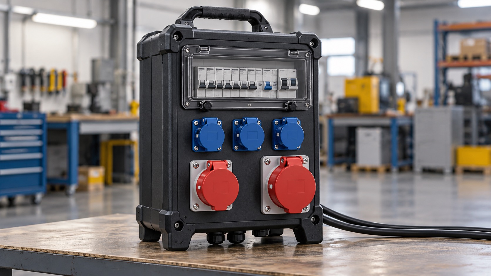
First, Confirm Which Functional Layer the Enclosure Is Responsible For
A single socket with a separate wiring enclosure addresses installation and wiring-space constraints but does not imply that the enclosure already includes power distribution, switching, or protective functions. Multi-position combination box puts multiple outlets into the same enclosure, but whether each outlet shares the incoming line, whether it adopts independent shunt, whether there is circuit breaker or residual current protection, still need to be confirmed item by item.
When a cabinet contains an incoming unit, internal conductors or busbars, multiple branch circuits, and protective devices, it shall be verified as a complete switchgear assembly. Don’t just ask “how many sockets”, but also ask where the electricity enters, how to distribute it to each outlet, which device protects which circuit, and what conditions the whole machine is designed for simultaneous use.
First Draw a Single-Line Diagram, Then Determine the Enclosure Configuration
A reliable quotation should begin with a single-line diagram or a circuit-by-circuit configuration table. First list the incoming power supply, grounding system and each planned load, and then write down the voltage, phase number, official pole position, maximum working current, starting characteristics and expected simultaneous usage of each outlet. When a three-phase input supplies multiple single-phase outlets, it is also necessary to plan the phase allocation and assess the neutral current.
In this step, you cannot simply add up the rated currents of all the outlets. Incoming lines, internal conductors or busbars, switches, protection devices, and the overall temperature rise design will limit the maximum simultaneous output. The supplier needs to specify the incoming line rating, the overall machine rating, each shunt rating and each interface rating, and provide the specified simultaneous load conditions.
The Interface Rating Does Not Substitute for the System Rating
The current marked on the socket only indicates the rated level of the interface under the specified conditions, and does not mean that the upstream circuit can provide the same current. The nameplate of a circuit breaker, isolator or socket cannot replace the rated voltage, rated current, short-circuit withstand or conditional short-circuit rating of the whole machine.
When mixing outlets of different voltages, currents or pole positions, each interface shall be clearly identified and powered and protected by the correct shunt. When the IEC 60309 interface is used, the rated current, number of poles, voltage, frequency and clock position of the protective conductor contacts shall be checked one by one. Similar appearance or color does not necessarily mean they can be safely paired.
Protection Settings Must Be Applied to Every Circuit
The name with MCB can only indicate that the miniature circuit breaker is declared in the configuration, and cannot indicate its rated current, number of poles, trip characteristics, breaking capacity or protection range. The overcurrent protection of each shunt should be coordinated with the conductor, terminal, socket and actual load, and the expected short-circuit current at the installation point cannot exceed the capacity allowed by the protection scheme.
Whether the residual current protection is configured, and what kind of action parameters and types are adopted shall be determined in combination with the grounding system, load characteristics, place of use and local rules. When maintenance and isolation are required, the isolation scope, disconnected conductors, locking method, and status indicators must also be specified. The ordinary switch has a handle, which does not mean that it naturally meets the isolation requirements; when it is necessary to avoid plugging and unplugging with load, it should be confirmed that the product has a clear interlocking action.
The IP Rating Should Be Interpreted Based on the Fully Assembled Condition
The IP rating on the enclosure is not a universal guarantee for all operating conditions. The door, socket cover, operating handle, observation window, inlet seal, unused opening and whether the plug is plugged or not will affect the protection conditions after the complete set. Even if the interface and the empty box have the target level respectively, the combined whole machine should still be confirmed according to the actual structure.
IP67 indicates dust and temporary immersion protection under specified conditions, which does not mean permanent immersion is allowed, nor can it prove resistance to high-pressure cleaning, corrosion, ultraviolet rays, chemical media or mechanical impact. If there is water spray, dust, condensation or impact on the site at the same time, the conditions should be proposed separately, and the total environmental risk should not be summarized by one IP grade.
Acceptance Should Not Be Limited to Collecting Component Certificates
Sockets, circuit breakers, isolating switches and enclosures meet product standards, and cannot automatically prove that the combined distribution box has met the requirements of the whole machine. As a low-voltage package, the applicable parts of the IEC 61439 series shall be confirmed according to the actual use; the applicable boundary between ordinary power distribution and construction site devices is not the same.
The design verification of the whole machine needs to cover the actual structure and rated conditions, including internal circuit, terminal, protective conductor loop, temperature rise, short circuit performance and shell protection. Each finished product shall also undergo the applicable routine verification. If the enclosure, busbars, protective devices, internal layout, or ventilation method are changed, the original verification shall be reassessed to determine whether it remains valid.
Match the Quotation Version With the Technical Documents
Before placing an order, the supplier is required to return the BOM, single-line diagram or wiring diagram, terminal and wire number, incoming and outgoing wire rating, protection device parameters, short circuit parameters, IP status, external dimensions and complete machine verification documents consistent with the quotation version. If replacement of in-box components is permitted, the replacement approval and re-validation boundaries should be agreed in advance, rather than only after delivery to discover that the make or model has changed.
Finally, align the model numbers, drawing versions, and verification documents on the quotation item by item. Only when each branch, each interface and the whole machine boundary can correspond in the same configuration can the distribution box truly enter a comparable and acceptable procurement state.